Which two statements distinguish authentication from accounting? (Choose two.)
A network engineer is configuring a new router at a branch office. The router is connected to an upstream WAN network that allows the branch to communicate with the head office. The central time server with IP address 172.24.54.8 is located behind a firewall at the head office. Which command must the engineer configure so that the software clock of the new router synchronizes with the time server?
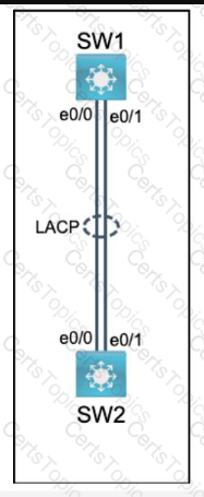
Physical connectivity is implemented between the two Layer 2 switches,
and the network connectivity between them must be configured.
I . Configure an LACP EtherChanneI and number it as 44; configure it
between switches SWI and SW2 using interfaces EthernetO/O and
Ethernet0/1 on both sides. The LACP mode must match on both ends.
2. Configure the EtherChanneI as a trunk link.
3. Configure the trunk link with 802. Iq tags.
4. Configure VLAN 'MONITORING' as the untagged VLAN of the
EtherChannel.
==================
Guidelines
This is a lab item in which tasks will be performed on virtual devices.
• Refer to the Tasks tab to view the tasks for this lab item.
• Refer to the Topology tab to access the device console(s) and perform the tasks.
• Console access is available for all required devices by clicking the device icon or using
the tab(s) above the console window.
• All necessary preconfigurations have been applied.
• Do not change the enable password or hostname for any device.
• Save your configurations to NVRAM before moving to the next item.
• Click Next at the bottom of the screen to submit this lab and move to the next question.
• When Next is clicked, the lab closes and cannot be reopened.
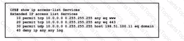
Refer to the exhibit. This ACL is configured to allow client access only to HTTP, HTTPS, and DNS services via UDP. The new administrator wants to add TCP access to the DNS service. Which configuration updates the ACL efficiently?
Copyright © 2021-2025 CertsTopics. All Rights Reserved