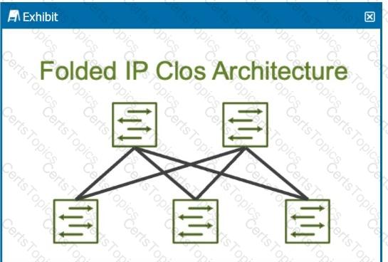
In modern data centers, the shift toward leaf-spine architectures is driven by the need to handle increased east-west traffic, which is traffic between servers within the same data center. Unlike traditional hierarchical data center designs, where most traffic was "north-south" (between users and servers), modern applications often involve server-to-server communication (east-west) to enable services like distributed databases, microservices, and virtualized workloads.
Leaf-Spine Architecture:
Leaf Layer: This layer consists of switches that connect directly to servers or end-host devices. These switches serve as the access layer.
Spine Layer: The spine layer comprises high-performance switches that provide interconnectivity between leaf switches. Each leaf switch connects to every spine switch, creating a non-blocking fabric that optimizes traffic flow within the data center.
East-West Traffic Accommodation:
In traditional three-tier architectures (core, aggregation, access), traffic had to traverse multiple layers, leading to bottlenecks when servers communicated with each other. Leaf-spine architectures address this by creating multiple equal-cost paths between leaf switches and the spine. Since each leaf switch connects directly to every spine switch, the architecture facilitates quick, low-latency communication between servers, which is essential for east-west traffic flows.
Juniper's Role:Juniper Networks provides a range of solutions that optimize for east-west traffic in a leaf-spine architecture, notably through:
QFX Series Switches: Juniper’s QFX series switches are designed for the leaf and spine architecture, delivering high throughput, low latency, and scalability to accommodate the traffic demands of modern data centers.
EVPN-VXLAN: Juniper uses EVPN-VXLAN to create a scalable Layer 2 and Layer 3 overlay network across the data center. This overlay helps enhance east-west traffic performance by enabling network segmentation and workload mobility across the entire fabric.
Key Features That Support East-West Traffic:
Equal-Cost Multipath (ECMP): ECMP enables the use of multiple paths between leaf and spine switches, balancing the traffic and preventing any one path from becoming a bottleneck. This is crucial in handling the high volume of east-west traffic.
Low Latency: Spine switches are typically high-performance devices that minimize the delay between leaf switches, which improves the efficiency of server-to-server communications.
Scalability: As the demand for east-west traffic grows, adding more leaf and spine switches is straightforward, maintaining consistent performance without redesigning the entire network.
In summary, the leaf-spine architecture is primarily designed to handle the increase ineast-west trafficwithin data centers, and Juniper provides robust solutions to enable this architecture through its switch platforms and software solutions like EVPN-VXLAN.


