What is the correct order of steps to create and operate a custom monitor?
The correct order of steps to create and operate a custom monitor is:
Determine the type and frequency of statistics to collect.
Create a monitor.
Add one or more sinks to the monitor.
Collect statistics.
Gather monitoring files, or monitor output from the console.
To create and operate a custom monitor within the Dell VPLEX environment, follow these steps:
Determine the Type and Frequency of Statistics to Collect: Identify what statistics are relevant for your monitoring purposes and how frequently they should be collected. This will depend on the specific needs of your environment and the performance metrics you wish to track.
Create a Monitor: Using the VPLEX CLI or Unisphere for VPLEX, create a new monitor instance. Configure the monitor with the types of statistics you determined in the previous step.
Add One or More Sinks to the Monitor: Sinks are the destinations where the collected statistics will be sent. These could be files, databases, or external systems. Set up one or more sinks in the monitor configuration to ensure that the data is stored or transmitted as needed.
Collect Statistics: Start the monitor to begin collecting statistics. The monitor will gather data from the VPLEX system according to the type and frequency settings you have specified.
Gather Monitoring Files, or Monitor Output from the Console: After the statistics have been collected, retrieve the monitoring files from the specified sinks, or view the output directly from the console if real-time monitoring is configured.
These steps are based on the standard procedures for setting up and managing custom monitors in a Dell VPLEX environment, as detailed in the Dell EMC VPLEX documentation. By following these steps, you can effectively monitor the performance and health of your VPLEX system.
A VPLEX Metro cluster is being installed for a company that is planning to create distributed volumes with 200 TB of storage. Based on this requirement, and consistent with
EMC best practices, what should be the minimum size for logging volumes at each cluster?
10 GB
. 12.5 GB
16.5 GB
20 GB
When configuring a VPLEX Metro cluster, especially for a company planning to create distributed volumes with a large amount of storage like 200 TB, it is essential to adhere to EMC best practices for the size of logging volumes.
Purpose of Logging Volumes: Logging volumes in VPLEX are used to store write logs that ensure data integrity and consistency across distributed volumes. These logs play a critical role during recovery processes1.
Size Considerations: The size of the logging volumes should be proportional to the amount of active data being written to ensure that all write operations are captured in the logs. For 200 TB of distributed storage, a minimum size of 10 GB for each logging volume is recommended to handle the logging requirements1.
Configuration: The logging volumes should be configured on each cluster to provide redundancy and high availability. This means that both clusters in a VPLEX Metro configuration should have logging volumes of at least the minimum recommended size1.
Best Practices: EMC best practices suggest that the logging volume should be sized appropriately to support the operational workload and to ensure that there is sufficient space to capture all write operations without any loss of data1.
Verification and Monitoring: After setting up the logging volumes, it is important to monitor their utilization to ensure they are functioning correctly and to adjust their size if necessary based on the actual workload1.
In summary, consistent with EMC best practices, the minimum size for logging volumes at each cluster in a VPLEX Metro cluster being installed for creating distributed volumes with 200 TB of storage should be 10 GB. This size ensures that the logging volumes can adequately support the write logging requirements for the amount of storage being used.
=========================
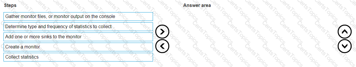
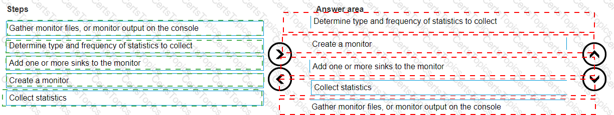
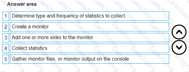
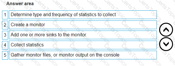
Which command is used to display available statistics for monitoring VPLEX?
monitor collect
monitor create
monitor add-sink
monitor stat-list
The command used to display available statistics for monitoring VPLEX is monitor stat-list. This command provides a list of all the statistics that can be monitored on the VPLEX system.
Command Usage: The monitor stat-list command is executed in the VPLEX CLI (Command Line Interface). When run, it will display a list of all the statistics that are available for monitoring1.
Monitoring Statistics: The statistics available for monitoring can include various performance metrics such as IOPS (Input/Output Operations Per Second), throughput, and latency. These metrics are crucial for assessing the health and performance of the VPLEX system1.
Custom Monitors: In addition to the default system monitors, custom monitors can be created to track specific data. The monitor stat-list command helps in identifying which statistics can be included in these custom monitors1.
Performance Analysis: By using the monitor stat-list command, administrators can determine which statistics are relevant for their performance analysis and can then create monitors to track those specific metrics1.
Documentation Reference: For more information on the usage of the monitor stat-list command and other monitoring commands, administrators should refer to the VPLEX CLI and Administration Guides for the code level the VPLEX is running1.
In summary, the monitor stat-list command is used to display the available statistics for monitoring VPLEX, providing administrators with the information needed to set up and manage performance monitoring on the system.
A RAID-C device has been built from a 100 GB extent and a 30 GB extent. How can this device be expanded?
RAID-C device cannot be expanded with unequal extent sizes
Add another RAID-C device to create a top-level device
Expand the 100 GB or 30 GB storage volume on the back-end array
Use concatenation by adding another extent to the device
To expand a RAID-C device that has been built from extents of unequal sizes, such as a 100 GB extent and a 30 GB extent, concatenation can be used. Concatenation allows for the addition of another extent to the existing RAID-C device, thereby increasing its overall size.
Understanding RAID-C: RAID-C is a type of RAID configuration used in VPLEX that allows for concatenation, which is the process of linking multiple storage extents to create a larger logical unit1.
Adding an Extent: To expand the RAID-C device, a new extent of the desired size can be added to the existing device. This new extent is concatenated to the end of the current extents, increasing the total capacity of the RAID-C device1.
VPLEX CLI Commands: The expansion is performed using VPLEX CLI commands. The specific command to add an extent to a RAID-C device would be similar to the storage-volume expand command, which instructs the system to include the new extent in the RAID-C device1.
Resizing Back-End Storage: If necessary, the back-end storage volumes (the physical storage on the array) that correspond to the extents may need to be resized to match the new configuration1.
Verification: After the expansion, it’s important to verify that the RAID-C device reflects the new size and that all extents are properly concatenated and functioning as expected1.
In summary, a RAID-C device built from extents of unequal sizes can be expanded by using concatenation to add another extent to the device. This method allows for flexibility in managing storage capacity within a VPLEX environment.
What are the two common use cases of the VPLEX Mobility feature?
Workload Rebalance
Deduplication
NDU upgrades
Continuous Data Protection
Workflow Automation
Tech Refresh
Tech Refresh
Workload Rebalance
The VPLEX Mobility feature is designed to address various operational needs in a data center environment. Two of the most common use cases for this feature are Tech Refresh and Workload Rebalance.
Tech Refresh: The Tech Refresh use case involves using VPLEX to migrate data from older storage arrays to newer ones without disrupting the applications. This is crucial for organizations that need to update their storage infrastructure without downtime1.
Workload Rebalance: Workload Rebalance refers to the ability to move workloads across different storage systems to balance performance and capacity needs. VPLEX enables this by allowing data to be moved non-disruptively, ensuring continuous application availability1.
Operational Flexibility: VPLEX Mobility provides operational flexibility by enabling data to be moved within the same data center, across a campus, or within a geographical region. This capability is essential for dynamic environments where workload demands can change rapidly1.
Enhanced Resource Utilization: By leveraging VPLEX Mobility for Tech Refresh and Workload Rebalance, organizations can optimize resource utilization, reduce operational costs, and improve overall system performance1.
Best Practices: It is recommended to follow Dell’s best practices when using VPLEX Mobility features. This includes planning migrations during low-activity periods and ensuring that all systems are properly zoned and configured1.
In summary, the two common use cases of the VPLEX Mobility feature are Tech Refresh, which allows for seamless data migrations during technology upgrades, and Workload Rebalance, which facilitates the dynamic allocation of resources to meet changing workload demands.
In preparing a host to access its storage from VPLEX, what is considered a best practice when zoning?
Each host should have at least one path to an A director and at least one path to a B director on each fabric, for a total of four logical paths.
Ports on host HBA should be zoned to either an A director or a B director.
Each host should have either one path to an A director or one path to a B director on each fabric, for a minimum of two logical paths.
Dual fabrics should be merged into a single fabric to ensure all zones are in a single zoneset.
What is an EMC best practice for connecting VPLEX to back-end arrays?
One multiple switch fabric should be used for each VPLEX engine
Back-end connections should be distributed across one director
Each VPLEX director should have four active paths to every back-end array storage volume
Two active paths per VPLEX engine to any storage volume is optimal
EMC recommends specific best practices for connecting VPLEX to back-end storage arrays to ensure high availability and optimal performance. One of these best practices is that each VPLEX director should have four active paths to every back-end array storage volume.
Multiple Paths: Having multiple active paths from each VPLEX director to the storage volumes ensures that there is no single point of failure. If one path fails, the other paths can continue to provide connectivity1.
Load Balancing: Multiple paths also allow for load balancing of I/O operations across the different paths, which can improve performance and reduce the risk of bottlenecks1.
Path Redundancy: Path redundancy is crucial for maintaining continuous availability, especially in environments where the VPLEX is used for mission-critical applications1.
Configuration: The configuration of the paths should be done in accordance with EMC’s best practices, which include proper zoning and masking in the SAN environment1.
Documentation: Detailed guidelines and best practices for VPLEX SAN connectivity, including back-end array connections, are available in EMC’s documentation, which provides comprehensive instructions for setting up and managing these connections1.
In summary, EMC’s best practice for connecting VPLEX to back-end arrays is to ensure that each VPLEX director has four active paths to every back-end array storage volume. This setup provides the necessary redundancy and performance for a robust and reliable storage environment.
=========================
What is the maximum number of synchronous consistency groups supported by VPLEX?
512
2048
1024
256
The maximum number of synchronous consistency groups supported by VPLEX is 256. This number is determined by the system’s capabilities and is designed to ensure optimal performance and manageability.
Consistency Groups: Consistency groups in VPLEX are used to group multiple virtual volumes together to ensure write-order fidelity, which is crucial for applications requiring transactional integrity12.
Synchronous Operations: Synchronous consistency groups are particularly important for environments where data must be kept consistent across geographically dispersed clusters in real-time12.
System Limitations: The limit of 256 synchronous consistency groups is set to balance the system’s performance with the need for data consistency. It ensures that the system can maintain the required performance levels while providing the data protection and availability features12.
Configuration and Management: Administrators must carefully plan and manage the consistency groups within the limits of the system to ensure that all critical data is protected and that the system operates efficiently12.
Documentation Reference: For detailed information on configuring and managing consistency groups, administrators should refer to the Dell VPLEX Deploy Achievement documents and best practice guides12.
In summary, the verified answer to the maximum number of synchronous consistency groups supported by VPLEX is 256. This limitation is part of the system design to ensure high availability and performance.
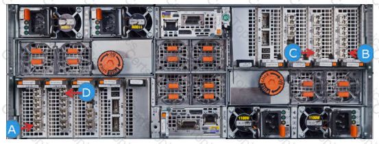
Refer to the exhibit.
Which Director-A port can be zoned to a host initiator?
B
C
D
A
In a VPLEX system, zoning a host initiator to a Director-A port requires identifying the front-end ports, which are used for host connectivity. Based on the standard VPLEX director port configuration:
Director Identification: Determine which unit is Director-A. In a VPLEX system, directors are typically labeled as A or B, and each has a set of front-end and back-end ports1.
Front-End Port Selection: The front-end ports on Director-A are used for connecting to host initiators. These ports are typically numbered starting with 01.
Zoning Process: Zoning involves configuring the SAN fabric to allow communication between the host’s HBA (Host Bus Adapter) and the VPLEX front-end port. This is done using the SAN switch management interface1.
Port Identification in Exhibit: Based on the exhibit provided, if the black arrow points to the first port on Director-A, it would be the front-end port 0, which can be zoned to a host initiator1.
Verification: To confirm the correct port for zoning, one would typically refer to the official Dell EMC VPLEX documentation for hardware installation and setup, which would provide clear labeling of each port1.
In summary, based on the standard VPLEX port configuration, the Director-A port that can be zoned to a host initiator is the front-end port 0, which is indicated by the letter D in the exhibit provided.
What is a consideration when using VPLEX RecoverPoint enabled consistency groups?
Production and local copy journals must be in different consistency groups.
Local copy volumes and production volumes must reside in separate consistency groups.
Repository volume and journal volumes must be in different consistency groups.
Local virtual volumes and distributed virtual volumes can be in the same consistency group.
When using VPLEX with RecoverPoint enabled consistency groups, it is important to ensure that local copy volumes and production volumes are placed in separate consistency groups. This separation is crucial for maintaining the integrity of the data replication and recovery processes.
Consistency Group Configuration: Consistency groups in VPLEX are logical groupings of virtual volumes that VPLEX treats as a single unit for operations such as data mobility and recovery. When RecoverPoint is enabled, these groups also align with RecoverPoint consistency groups for replication purposes1.
Separation of Volumes: Keeping local copy volumes (volumes used for local replication) and production volumes (active volumes serving data to hosts) in separate consistency groups helps to prevent any potential conflicts or issues with replication and ensures that the local copies are consistent and usable for recovery1.
RecoverPoint Replication: RecoverPoint provides continuous data protection and replication for recovery to any point in time. The separation of volumes into different consistency groups helps to manage and maintain the replication process effectively1.
Operational Management: By separating these volumes into different consistency groups, administrators can manage operations such as replication, failover, and recovery with greater precision and control1.
Best Practices: This separation is part of the best practices recommended by Dell EMC when configuring VPLEX with RecoverPoint, ensuring that the system operates efficiently and that data is protected in case of any failures1.
In summary, when using VPLEX with RecoverPoint enabled consistency groups, local copy volumes and production volumes must be placed in separate consistency groups to ensure proper replication and recovery processes.
When using the VIAS method of storage provisioning after selecting a cluster, what determines the set of arrays available from which to provision storage?
Array Management Provider registered for each cluster only
Array Management Provider registered for each clusterArrays zoned to VPLEX BE
Arrays zoned to VPLEX BE for the selected cluster only
Arrays that are claimed in each VPLEX cluster
When using the Virtual Integrated Aggregate Storage (VIAS) method of storage provisioning in Dell VPLEX, the set of arrays available for provisioning storage is determined by the Array Management Provider (AMP) registered for each cluster. The AMP is responsible for managing the communication between the VPLEX and the back-end storage arrays.
Array Management Provider (AMP): The AMP is a software component that interfaces with the storage arrays to facilitate storage provisioning, monitoring, and management. It must be registered with each VPLEX cluster to manage the arrays1.
VIAS Provisioning: VIAS is a feature in VPLEX that simplifies the provisioning process by integrating with the AMP to provide a single interface for storage provisioning across multiple heterogeneous arrays1.
Cluster Selection: After selecting a cluster in the VIAS interface, the AMP registered for that particular cluster determines which arrays are available for provisioning. This ensures that storage is provisioned from arrays that are managed by the cluster’s AMP1.
Provisioning Process: The administrator can then select the appropriate array from the list provided by the AMP and proceed with the storage provisioning process using the VIAS interface1.
Best Practices: It is recommended to follow Dell EMC’s best practices for registering and configuring the AMP with VPLEX to ensure seamless storage provisioning and management1.
In summary, when using the VIAS method of storage provisioning in Dell VPLEX, the set of arrays available from which to provision storage is determined by the Array Management Provider registered for each cluster only.
A storage administrator created a local RAID-0 virtual volume. However, the administrator decided to increase data protection by requiring a distributed virtual volume.
What is the recommended method to change the local volume to a distributed volume?
Place the volume in a consistency group and enable remote access
Create a device on the remote cluster without a virtual volume and attach it as a mirror
Use device migration to move the device to cluster-2
Use VIAS to create a new distributed device, then perform a device migration
To increase data protection by converting a local RAID-0 virtual volume to a distributed virtual volume, the recommended method is to create a corresponding device on the remote cluster and then attach it as a mirror to the existing local device. This process effectively creates a distributed virtual volume that spans across both clusters.
Create a Device on the Remote Cluster: Start by creating a new device on the remote VPLEX cluster. This device should be of the same size as the local RAID-0 virtual volume and should not have a virtual volume associated with it1.
Attach as a Mirror: Once the remote device is created, attach it as a mirror to the local RAID-0 virtual volume. This operation is performed using the VPLEX CLI and will begin the process of mirroring the data from the local device to the remote device1.
Synchronization: After attaching the remote device as a mirror, the VPLEX system will synchronize the data between the local and remote devices. This ensures that both devices have identical data and are in a consistent state1.
Distributed Virtual Volume: Once the synchronization is complete, the local and remote devices together form a distributed virtual volume. This volume now has increased data protection because it is distributed across two different clusters1.
Verification: Verify that the distributed virtual volume is functioning correctly by checking its status and ensuring that it is accessible from both clusters1.
Best Practices: It is important to follow the best practices for creating and managing distributed virtual volumes as outlined in the Dell VPLEX Deploy Achievement documents. This includes proper planning, execution, and verification of the mirroring process1.
In summary, the recommended method to change a local RAID-0 virtual volume to a distributed virtual volume is to create a corresponding device on the remote cluster and attach it as a mirror, thereby forming a distributed virtual volume with increased data protection.
A customer engineer has installed VS2 VPLEX hardware, assigned IPs, and made the VPLEX ready to be configured. Which interface and port should be used to ssh to when
using the EZ Setup wizard?
MMCS-B; eth3
MMCS-A; eth3
Management Server; eth3
Management Server; eth1
When using the EZ Setup wizard for VPLEX, the correct interface and port to SSH into is the Management Server’s eth1 interface. This is typically the interface configured for management access and is used during the initial setup process.
Management Server Access: The Management Server is the primary interface for managing and configuring the VPLEX system. It is through this server that the EZ Setup wizard is accessed1.
eth1 Interface: The eth1 interface on the Management Server is usually dedicated to management traffic. This interface is configured with an IP address that allows SSH access for configuration purposes1.
EZ Setup Wizard: The EZ Setup wizard is a guided setup tool that simplifies the initial configuration of the VPLEX system. It prompts the user for necessary information to configure the system1.
SSH Protocol: Secure Shell (SSH) is a network protocol used to securely access network services over an unsecured network. When configuring VPLEX, SSH is used to connect to the Management Server and run the EZ Setup wizard1.
Configuration Steps: To SSH into the Management Server, the customer engineer would use an SSH client, input the IP address assigned to the eth1 interface, and connect using the appropriate credentials provided during the VPLEX installation1.
In summary, to use the EZ Setup wizard for configuring VPLEX, the customer engineer should SSH into the Management Server using the eth1 interface. This interface is set up during the initial installation and is used for management access to the system.
What information is required to configure ESRS for VPLEX?
VPLEX Model Type
Top Level Assembly
Site ID
IP address of the Management Server public port
ESRS Gateway Account
Site ID
VPLEX configuration
Top Level Assembly
IP Address of the Management Server public port
Front-end and Back-end connectivity
IP subnets
Putty utility
Site ID
VPLEX Site Preparation Guide
VPLEX configuration
VPLEX model type
To configure EMC Secure Remote Services (ESRS) for VPLEX, certain key pieces of information are required:
ESRS Gateway Account: An account on the ESRS Gateway is necessary to enable secure communication between the VPLEX system and EMC’s support infrastructure1.
Site ID: The Site ID uniquely identifies the location of the VPLEX system and is used by EMC support to track and manage service requests1.
VPLEX Configuration: Details of the VPLEX configuration, including the number of engines, clusters, and connectivity options, are required to properly set up ESRS monitoring1.
Top Level Assembly: The Top Level Assembly number is a unique identifier for the VPLEX system that helps EMC support to quickly access system details and configuration1.
These details are essential for setting up ESRS, which allows for proactive monitoring and remote support capabilities for the VPLEX system. The ESRS configuration ensures that EMC can provide timely and effective support services.
Which type of statistics is used to track latencies, determine median, mode, percentiles, minimums, and maximums?
Buckets
Readings
Monitors
Counters
In the context of performance monitoring, particularly for systems like Dell VPLEX, histograms are used to track latencies and display statistical data such as median, mode, percentiles, minimums, and maximums. The term “buckets” is often used to describe the segments within a histogram that categorize the latency data into ranges. Each bucket represents a range of latencies, and the number of events (or I/O operations) that fall into each latency range is counted and displayed.
Histograms in Monitoring: Histograms provide a visual representation of how data is distributed across different ranges of values, which is particularly useful for understanding the performance characteristics of a system like VPLEX.
Buckets Explained: Buckets within a histogram divide the entire range of collected data into discrete intervals. For latency tracking, these buckets might represent latency ranges such as 0-1 ms, 1-2 ms, etc.
Latency Tracking: By collecting latency data in buckets, administrators can quickly identify the distribution of latencies over time, pinpointing whether most I/O operations are fast, slow, or somewhere in between.
Minimums and Maximums: Histograms make it easy to see the minimum and maximum latencies experienced by the system, as well as the frequency of latencies within each bucket range.
Performance Analysis: This method of collecting and analyzing performance statistics is crucial for performance tuning and capacity planning, as it helps administrators understand the behavior of their storage systems under different workloads.
In summary, “buckets” are the correct answer when referring to the segments within a histogram that are used to collect and categorize latency data for performance monitoring purposes in systems like Dell VPLEX.
What are the requirements to upgrade a VPLEX from VS2 to VS6?
GeoSynchrony 6.0 minimum
Both VS2 and VS6 at same code level
Same number of engines
WWN zoning
GeoSynchrony 5.0 minimum
Both VS2 and VS6 at same code level
Same number of engines
WWN zoning
GeoSynchrony 6.0 minimum
Both VS2 and VS6 at same code level
Same number of engines
WWN zoning and temporary FC Local COM I/O modules in VS2
GeoSynchrony 6.0 minimum
Both VS2 and VS6 at same code level
Same number of engines
WWN zoning and temporary FC Local COM I/O modules in VS6
Upgrading a VPLEX from VS2 to VS6 hardware involves several critical requirements to ensure a successful and non-disruptive process:
GeoSynchrony Version: The system must be running at least GeoSynchrony 6.0. This is the software that orchestrates operations across the VPLEX infrastructure and ensures compatibility between different hardware generations1.
Code Level Consistency: Both the VS2 and VS6 platforms must be operating at the same software code level. This uniformity is crucial to prevent any incompatibility issues during the upgrade process1.
Engine Count: The number of engines in the existing VS2 setup must match the number of engines in the VS6 configuration. This alignment is necessary to maintain performance and capacity expectations post-upgrade1.
WWN Zoning: Proper WWN (World Wide Name) zoning must be in place. WWN zoning is a method of isolating network traffic to ensure that devices within a Fibre Channel network can only communicate with each other if they are in the same zone1.
Upgrade Process: The upgrade process typically involves replacing the VS2 hardware with VS6 components. This hardware swap should be done in a manner that does not disrupt the ongoing operations and services1.
Post-Upgrade Verification: After the hardware upgrade, it’s essential to verify that all systems are functioning correctly. This includes checking the status of the front-end and back-end ports, as well as the health of the virtual volumes1.
Documentation and Support: Detailed procedures for the upgrade process can be found in the SolVe Desktop Procedure Generator, which provides step-by-step instructions for upgrading cluster hardware from VS2 to VS61.
In summary, the requirements for upgrading a VPLEX from VS2 to VS6 include running GeoSynchrony 6.0 or higher, ensuring both platforms are at the same code level, matching the number of engines, and having proper WWN zoning in place.
Which performance statistics are collected as histograms and used to track latencies to display minimums and maximums?
Buckets
Counters
Intervals
Readings
In the context of performance monitoring, particularly for systems like Dell VPLEX, histograms are used to track latencies and display minimums, maximums, and other statistical data. The term “buckets” is often used to describe the segments within a histogram that categorize the latency data into ranges. Each bucket represents a range of latencies, and the number of events (or I/O operations) that fall into each latency range is counted and displayed1.
Histograms in Monitoring: Histograms provide a visual representation of how data is distributed across different ranges of values, which is particularly useful for understanding the performance characteristics of a system like VPLEX1.
Buckets Explained: Buckets within a histogram divide the entire range of collected data into discrete intervals. For latency tracking, these buckets might represent latency ranges such as 0-1 ms, 1-2 ms, etc1.
Latency Tracking: By collecting latency data in buckets, administrators can quickly identify the distribution of latencies over time, pinpointing whether most I/O operations are fast, slow, or somewhere in between1.
Minimums and Maximums: Histograms make it easy to see the minimum and maximum latencies experienced by the system, as well as the frequency of latencies within each bucket range1.
Performance Analysis: This method of collecting and analyzing performance statistics is crucial for performance tuning and capacity planning, as it helps administrators understand the behavior of their storage systems under different workloads1.
In summary, “buckets” are the correct answer when referring to the segments within a histogram that are used to collect and categorize latency data for performance monitoring purposes in systems like Dell VPLEX.
How many copies can RecoverPoint maintain in a MetroPoint topology?
8
6
4
5
"The MetroPoint topology can maintain up to five copies of data, including one remote copy and one local copy at each VPLEX site. It provides protection for each of the VPLEX Metro sites with continuous local replication via RecoverPoint"..
Copyright © 2014-2024 CertsTopics. All Rights Reserved